01
ExposeLay the camera on its back. Lift the rubber cover to expose the chassis screws. Remove those screws, the rubber flap can remain attached.
FIG 1 FIG 1
FIG 1Transform the original BMPCC from static to tilt. Work each stage, tick the steps, clear the checkpoint, move on.
Contents
Before you start
While your backplate is being machined, 3D print the enclosure and order the parts using the parts list in your purchase.
The LCD enclosure and its top cover are printed parts. Print them in a high-temp filament: ABS, ASA, PC or PA nylon. High-temp PETG works too. PLA is NOT suitable.
The enclosure takes 4 threaded brass inserts for the M3 hinge screws. A heat-set insert kit is essential. Preferably use a soldering iron held in a press to seat each insert straight and flush.
Prep · quick inventory
Open the rear cover without stressing the internal FPC cables.
Lay the camera on its back. Lift the rubber cover to expose the chassis screws. Remove those screws, the rubber flap can remain attached.
FIG 1FIG 1Lift the camera from the bottom edges to keep it together.
FIG 2 FIG 2
FIG 2Set the camera on its side. Separate gently so the FPC cables are not stressed.
FIG 3 FIG 3
FIG 3With the battery door facing up, detach and slide toward the gap and remove. Keep the spring and center pin together.
FIG 4 FIG 4
FIG 4Lift the rear cover to expose the main board. Release or flip the FPC locking tabs and withdraw the cables.
FIG 6 · FIG 5 FIG 6
FIG 6 FIG 5
FIG 5Release the original LCD from the housing and set it aside.
Remove the screws holding the metal plate that secures the screen in place.
FIG 7 FIG 7
FIG 7Use the spudger to lift the cover. It may be a bit tight if it has never been removed before.
FIG 8 FIG 8
FIG 8Push gently on the LCD to release it out of its seat and set it aside.
FIG 9 FIG 9
FIG 9Create an insulating layer and keep openings clear.
Lay the 20 mm BGA tape on the aluminum backplate. Press the tape into the sides with a spudger. Trim the excess.
FIG 10 FIG 10
Work out trapped air bubbles with the second spudger or flat edge.
FIG 11 FIG 11
At the FPC exit, ensure it is not blocked by the tape.
FIG 12 FIG 12
Insert the backplate into the housing.
FIG 13 FIG 13
Seat the backplate into the housing. Confirm it is fully seated.
FIG 14 FIG 14
Add insulation wherever the FPC would sit against bare aluminum.
Add BGA tape where the FPC cable would touch the aluminum.
FIG 15 FIG 15
Do the same on the screen where the FPC folds inside the housing.
FIG 16 FIG 16
Connect the LCD, route the extension FPC, then build the hinged enclosure.
Place the LCD FPC in the connector; the connector locking pins facing up and FPC contact pins facing down, latch the locking tab.
FIG 17 FIG 17
Test fit the connector in the enclosure slot.
FIG 18 FIG 18
Latch the extension FPC, secure the locking tab.
FIG 19 FIG 19
Bend the FPC in slightly and fold it to shorten its length.
FIG 20 FIG 20
Fit the top cover with four M2 screws. Leave them slightly loose for length adjustment.
FIG 21 FIG 21
Secure the hinges with the M3 screws.
FIG 22 FIG 22
Feed the FPC through the backplate slot before lining up the hinge holes.
FIG 23 FIG 23
Check that the LCD plate and housing rotate smoothly.
FIG 24 FIG 24
Nothing should be placed on the Main PCB. Conductive contact across it during power up can make the camera inoperable.
If you are not comfortable with this step, stop and put the camera back as it was.
Prove a clean LCD image before you commit to reassembly.
Make sure nothing is touching the Main PCB.
NO FIGURESlightly extend the LCD housing outward so the assembly cannot tip.
FIG 25 FIG 25
Connect the FPC extension to the camera.
FIG 26 FIG 26
Connect the battery or power supply and press the power button.
FIG 27 FIG 27
View the screen from several angles. Look for lines on the screen.
NO FIGUREIf lines appear, power down, disconnect, reseat the FPC and retest. If it persists, ensure all connectors are properly seated. If this still doesn't work, you may have a defective FPC cable, use the second one.
NO FIGURESecure the rear plate, adjust the cable length, reconnect the camera and close the body.
Loosely secure LCD securing plate with two screws so the FPC stays adjustable.
FIG 28 FIG 28
Roughly match the LCD and menu button cable lengths. Route the FPC with the tilt at full extension so it has slack to reach the connector and move freely.
FIG 29 FIG 29
Reconnect the LCD FPC and secure it with the locking tab.
FIG 30 FIG 30
Connect the menu FPC and secure it. Ensure each securing tab is closed. If all lengths are adequate, tighten all 5 plate screws. Do not skip this step, a loose screw can short the main PCB.
FIG 31 FIG 31
Center the battery door pin and use tweezers or a pin to reposition the spring so it sits against the body of the camera.
FIG 32 FIG 32
Carefully place the camera facing up to expose the securing screw holes. Fit the remaining body screws. Press the rubber cover back into place.
FIG 33 FIG 33
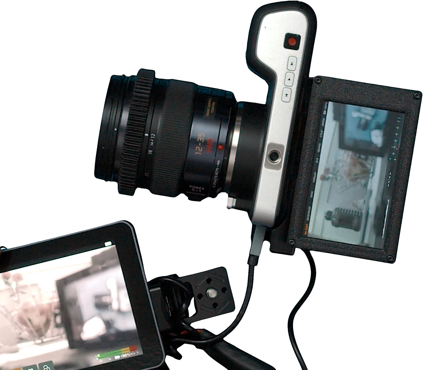
The relocated LCD works through the full range of movement.
Power on. Check again for lines on the LCD.
FIG 34 FIG 34
Mount a lens.
FIG 35 FIG 35
Flip the screen up. Confirm a live image is visible.
FIG 36 FIG 36
Confirm the relocated LCD tilts and works as expected.
FIG 37 FIG 37
Lock the HDMI output so it cannot pull free in use.
Use a SmallRig HDMI Type D (micro) to Type A adapter.
FIG 32 FIG 32
Attach the MagicRig HDMI cable clamp: back the moving jaw out, make sure the fixed jaw is against the HDMI cable, then tighten the 1/4-20 to the side of the rear plate. The knob can now be tightened onto the micro-HDMI plug. A printable screw attachment secures the HDMI out to the MagicRig.
FIG 31 FIG 31
Pull heat back out through the same path the backplate carries it in.
The aluminum backplate holds heat. The cooler mounts against the backplate and cools through the same path.
FIG 33 FIG 33
Build complete
The core build is done when the LCD is secure, the FPC moves freely, and the final live-image test passes.